Amateur ExtraE6C10
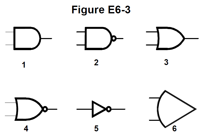
In Figure E6-3, which is the schematic symbol for a NOR gate?
D
Answer
Components and circuit devices
Type
A
1
B
2
C
3
D
4
Answer Notes
A NOR gate combines an OR gate with a NOT gate (inverter). The standard symbol for an OR gate has a curved input side and a pointed shield-like output side.
To make it a NOR gate, a small circle (inversion bubble) is added to the pointed output. In Figure E6-3, symbol 4 shows this exact shape: a curved input side, a pointed output, and a small circle.
Symbol 3 represents a regular OR gate (no circle), while symbols 1 and 2 represent AND and NAND gates, respectively.
Previous · E6C09
What is used to design the configuration of a field-programmable gate array (FPGA)?
Next · E6C11
In Figure E6-3, which is the schematic symbol for the NOT operation (inversion)?