Amateur ExtraE9G06
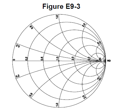
On the Smith chart shown in Figure E9-3, what is the name for the large outer circle on which the reactance arcs terminate?
B
Answer
Antennas and transmission lines
Type
A
Prime axis
B
Reactance axis
C
Impedance axis
D
Polar axis
Answer Notes
The Smith chart is constructed using two main sets of lines: circles of constant resistance and arcs of constant reactance. All the curved arcs that sweep vertically across the chart represent different reactance values.
These reactance arcs eventually terminate on the large, outermost boundary circle of the chart. This outer boundary is formally known as the reactance axis.
It represents a condition where the resistance is exactly zero. Any point located on this outer circle is a pure reactance, with inductive values on the top half and capacitive values on the bottom half. Distractors like 'Impedance axis' or 'Polar axis' are incorrect terminology for this specific boundary.
Previous · E9G05
Which of the following is a common use for a Smith chart?
Next · E9G07
On the Smith chart shown in Figure E9-3, what is the only straight line shown?