Technician 2026-2030T6C08
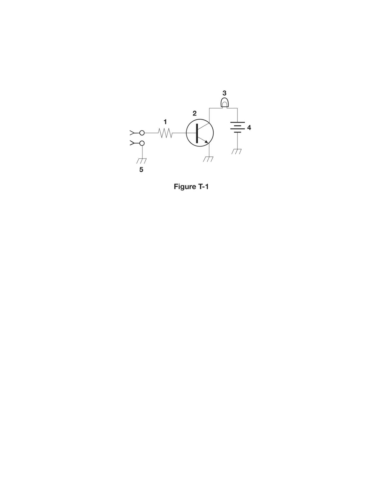
What is component 9 in figure T-2?
C
Answer
Electronic components and circuits
Type
A
Variable capacitor
B
Variable inductor
C
Variable resistor
D
Variable transformer
Answer Notes
In Figure T-2, component 9 is drawn as a zig-zag line with an arrow pointing to or passing through it. The zig-zag line is the standard symbol for a resistor, and the addition of an arrow indicates that its value can be adjusted, making it a variable resistor (often called a potentiometer).
In electronic schematic diagrams, an arrow drawn through or pointing to a standard component symbol universally means "variable" or "adjustable." This allows the user to change the resistance to control current or voltage in the circuit.
It cannot be a variable capacitor or variable inductor, as those would use the parallel plate or coiled wire symbols, respectively, rather than a zig-zag line.
Previous · T6C07
What is component 8 in figure T-2?
Next · T6C09
What is component 4 in figure T-2?