Amateur ExtraE7G07
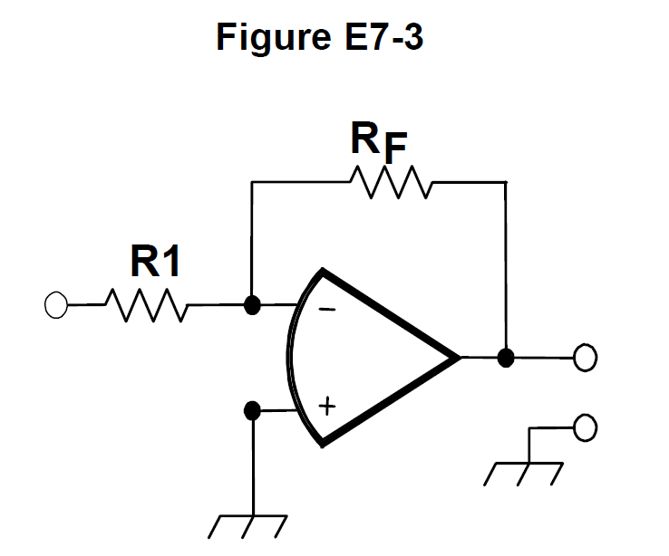
What voltage gain can be expected from the circuit in Figure E7-3 when R1 is 10 ohms and RF is 470 ohms?
C
Answer
Practical circuits and system design
Type
A
0.21
B
4700
C
47
D
24
Answer Notes
Figure E7-3 in the US Extra class exam pool represents a standard inverting operational amplifier circuit. The voltage gain for an inverting op-amp is determined by the ratio of the feedback resistor (RF) to the input resistor (R1), using the formula: Gain = RF / R1.
Plugging in the given values, we divide 470 ohms by 10 ohms to get an absolute voltage gain of 47. (The technical formula includes a negative sign, -RF/R1, to indicate phase inversion, but the magnitude of the gain is simply 47).
Distractors such as 4700 or 0.21 result from multiplying the values or dividing them in the wrong order. Remembering that the feedback resistor goes on top of the division ratio will reliably get you the correct answer.
Previous · E7G06
What is the gain-bandwidth of an operational amplifier?
Next · E7G08
How does the gain of an ideal operational amplifier vary with frequency?