Technician 2022-2026T6C03
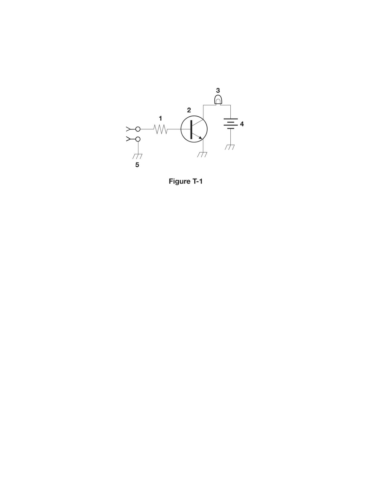
What is component 2 in figure T-1?
B
Answer
Electronic components and circuits
Type
A
Resistor
B
Transistor
C
Indicator lamp
D
Connector
Answer Notes
In standard exam Figure T-1, component 2 is depicted as a circle enclosing a flat vertical line with three connecting leads, where one lead has a small arrow. This is the standard schematic symbol for a bipolar junction transistor (BJT).
The three leads correspond directly to the transistor's electrodes: the emitter (the angled lead with the arrow), the base (the flat middle line), and the collector (the other angled plain line). The direction of the arrow indicates whether it is an NPN or PNP transistor.
Other options are incorrect because their standard symbols look completely different. For example, an indicator lamp is usually drawn as a circle containing an 'X' or a curved filament bump, and a resistor is drawn as a zigzag line.
Previous · T6C02
What is component 1 in figure T-1?
Next · T6C04
What is component 3 in figure T-1?