Technician 2022-2026T6C09
What is component 4 in figure T-2?
D
Answer
Electronic components and circuits
Type
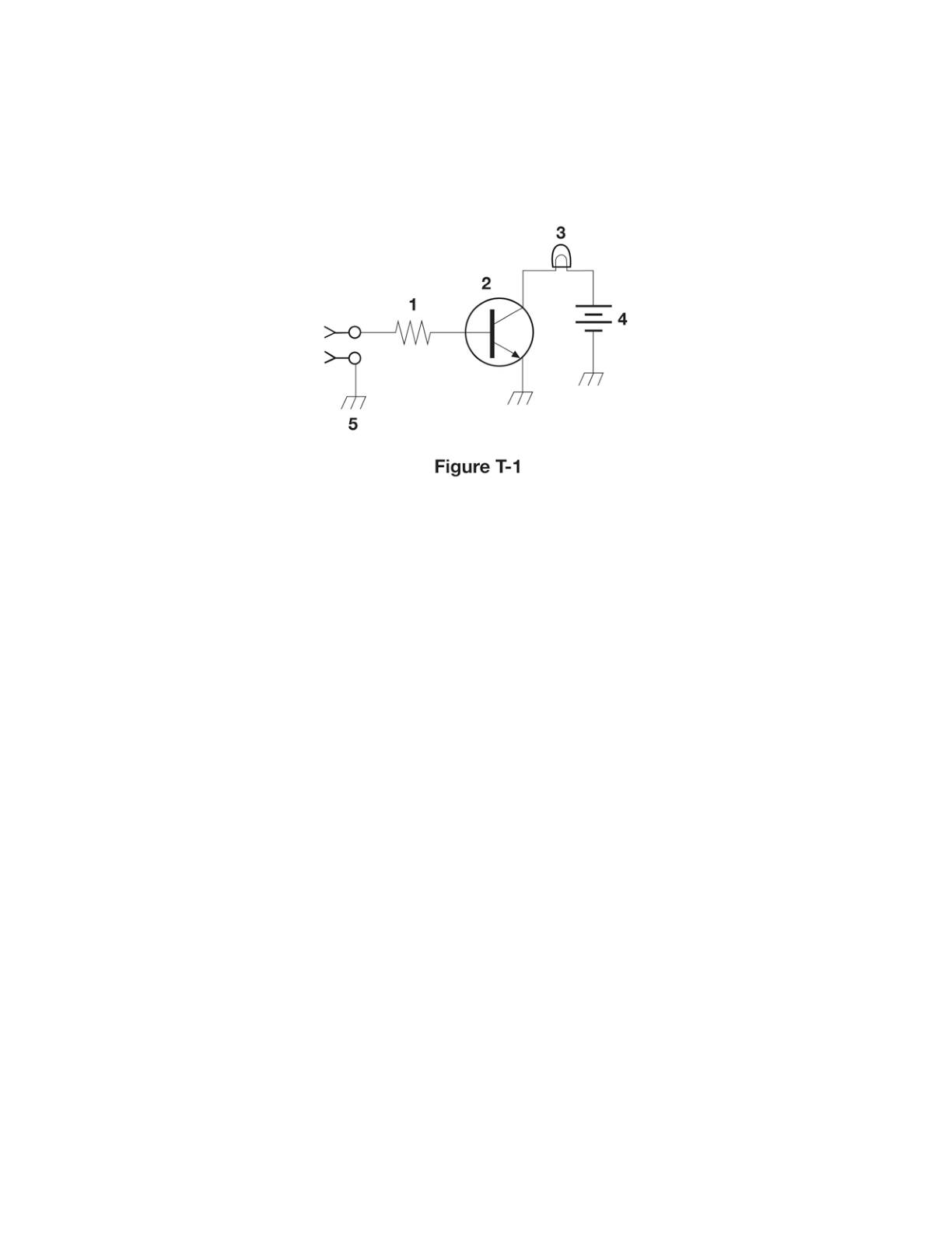
A
Variable inductor
B
Double-pole switch
C
Potentiometer
D
Transformer
Answer Notes
A transformer is represented in a schematic diagram by two separate inductor coils drawn side-by-side. Often, there are two solid parallel lines drawn between the coils to indicate that they share a magnetic iron core. This dual-coil structure perfectly describes component 4 in Figure T-2.
It is not a double-pole switch, which would look like two separate lines breaking a circuit simultaneously. It is also not a variable inductor or potentiometer, as those are single components (a single coil or a single zigzag line, respectively) with an arrow indicating adjustability.
Previous · T6C08
What is component 9 in figure T-2?
Next · T6C10
What is component 3 in figure T-3?