Technician 2022-2026T6C10
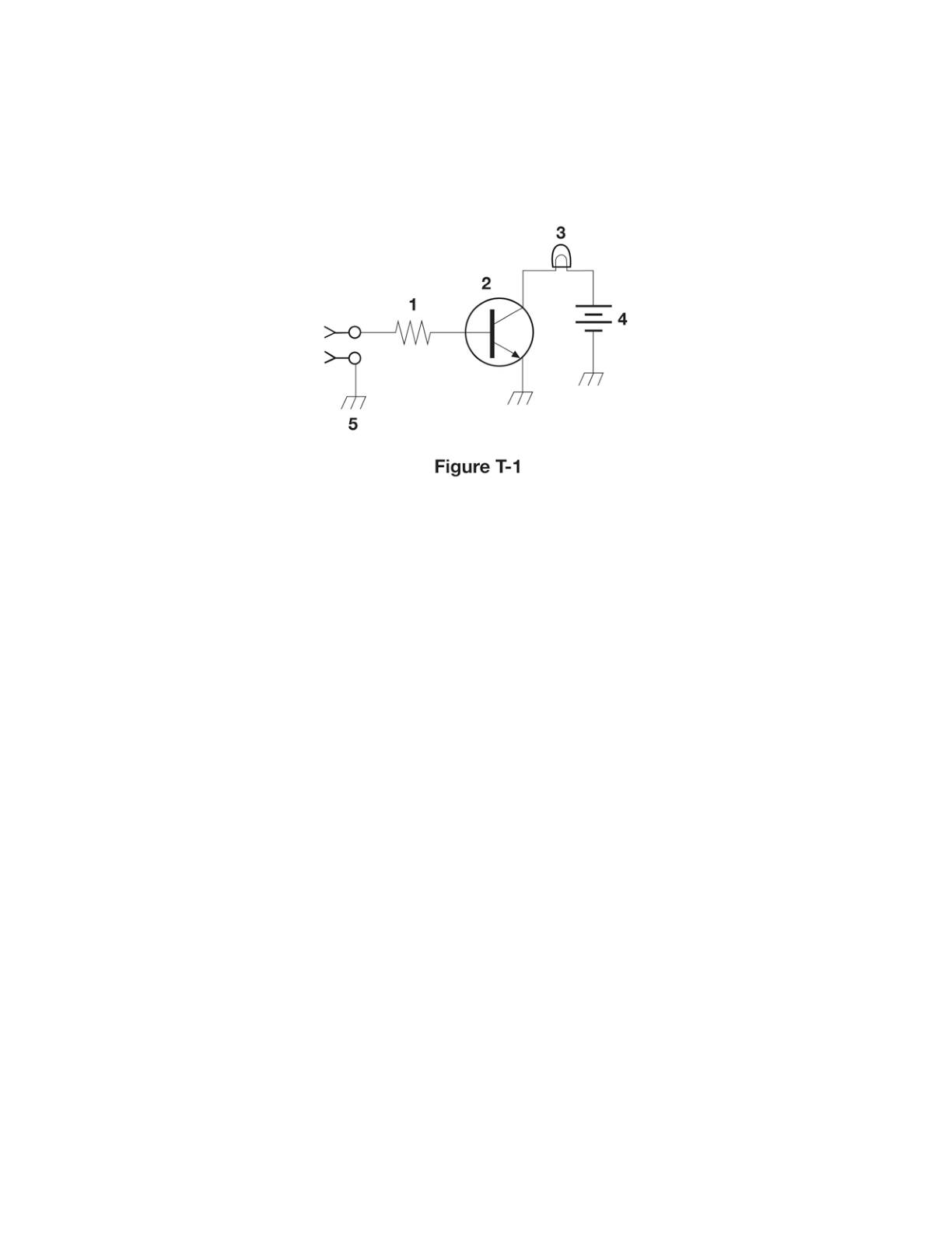
What is component 3 in figure T-3?
D
Answer
Electronic components and circuits
Type
A
Connector
B
Meter
C
Variable capacitor
D
Variable inductor
Answer Notes
In schematic diagrams, an inductor is represented by a series of curved loops or a coiled wire. When an arrow is drawn diagonally through the loops or pointing to them, it indicates that the inductance value can be adjusted. Thus, component 3 in Figure T-3 is a variable inductor.
It cannot be a variable capacitor, which uses parallel flat lines instead of loops. It is also not a connector or a meter, as those have entirely different standardized symbols, such as a circle with a letter inside for a meter.
Previous · T6C09
What is component 4 in figure T-2?
Next · T6C11
What is component 4 in figure T-3?