Amateur ExtraE7B10
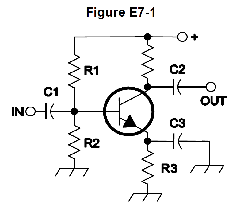
In Figure E7-1, what is the purpose of R1 and R2?
B
Answer
Practical circuits and system design
Type
A
Load resistors
B
Voltage divider bias
C
Self bias
D
Feedback
Answer Notes
In classic bipolar junction transistor (BJT) amplifier diagrams like Figure E7-1, R1 and R2 are arranged in series across the DC power supply, with the transistor's base connected to the junction between the two resistors. This specific arrangement forms a voltage divider network.
The purpose of this voltage divider is to provide a stable, predetermined DC bias voltage to the base of the transistor. This ensures the transistor rests at the correct operating point (quiescent point) in its active region so it can amplify AC signals without distortion. They are not load resistors, which would typically sit on the output side of the circuit.
Previous · E7B09
What is characteristic of an emitter follower (or common collector) amplifier?
Next · E7B11
In Figure E7-1, what is the purpose of R3?