Amateur ExtraE7B12
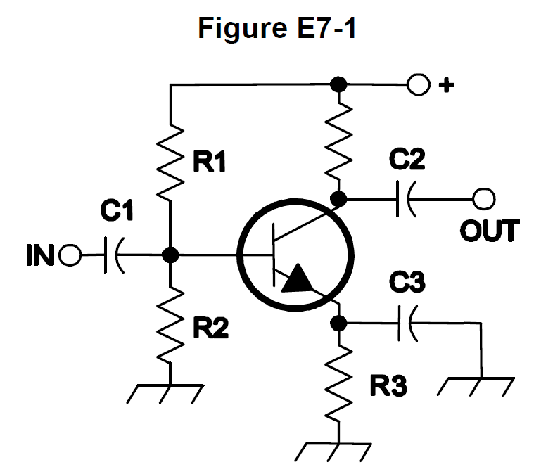
What type of amplifier circuit is shown in Figure E7-1?
C
Answer
Practical circuits and system design
Type
A
Common base
B
Common collector
C
Common emitter
D
Emitter follower
Answer Notes
In Figure E7-1 of the exam pool, the input signal is applied to the base of the bipolar junction transistor (BJT) and the output is taken from the collector. The emitter terminal is shared by both the input and output circuits, typically connected to ground or AC-grounded via a bypass capacitor. This configuration is known as a common emitter amplifier.
The common emitter is the most widely used transistor amplifier configuration because it provides both good voltage gain and good current gain. If the output were taken from the emitter instead, it would be a common collector (also known as an emitter follower) circuit.
To readily identify the 'common' element in any basic transistor amplifier diagram, look for the terminal that does not serve as either the primary signal input or the primary signal output.
Previous · E7B11
In Figure E7-1, what is the purpose of R3?
Next · E7C01
How are the capacitors and inductors of a low-pass filter Pi-network arranged between the network’s input and output?