Amateur ExtraE7D06
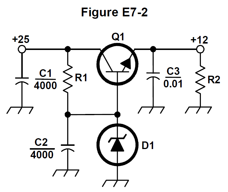
What is the purpose of Q1 in the circuit shown in Figure E7-2?
C
Answer
Practical circuits and system design
Type
A
It provides negative feedback to improve regulation
B
It provides a constant load for the voltage source
C
It controls the current to keep the output voltage constant
D
It provides regulation by switching or “chopping” the input DC voltage
Answer Notes
In the standard linear voltage regulator schematic (Figure E7-2), Q1 serves as the series pass transistor. It is positioned in series between the unregulated input voltage and the output load.
Q1 operates in its active, linear region, effectively acting like an automatically variable resistor. By adjusting the current it allows to pass through to the load based on a reference voltage, it continuously compensates for variations in input voltage or load current, keeping the output voltage constant.
Distractors suggesting the transistor 'chops' or switches the voltage are incorrect, as that describes the operation of a switching regulator, not a linear series regulator.
Previous · E7D05
Which of the following types of linear voltage regulator operates by loading the unregulated voltage source?
Next · E7D07
What is the purpose of C2 in the circuit shown in Figure E7-2?