Amateur ExtraE7D08
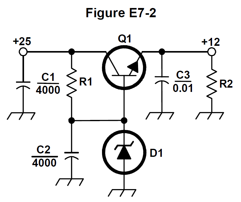
What type of circuit is shown in Figure E7-2?
C
Answer
Practical circuits and system design
Type
A
Switching voltage regulator
B
Common emitter amplifier
C
Linear voltage regulator
D
Common base amplifier
Answer Notes
Figure E7-2 depicts a classic linear voltage regulator. Specifically, it uses a series pass transistor (Q1) driven by a Zener diode reference to maintain a steady, regulated DC output voltage.
The circuit is called 'linear' because the regulating transistor operates in its active, linear region—acting as a continuously variable resistor to drop excess voltage. This is in stark contrast to a switching regulator, which rapidly toggles transistors fully on and off.
While the circuit uses a transistor, its configuration is entirely designed for power supply voltage regulation rather than amplifying RF or audio signals, which eliminates the common emitter or common base amplifier distractors.
Previous · E7D07
What is the purpose of C2 in the circuit shown in Figure E7-2?
Next · E7D09
How is battery operating time calculated?