Amateur ExtraE7D07
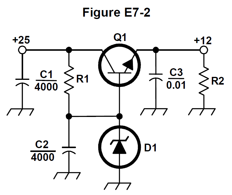
What is the purpose of C2 in the circuit shown in Figure E7-2?
A
Answer
Practical circuits and system design
Type
A
It bypasses rectifier output ripple around D1
B
It is a brute force filter for the output
C
To prevent self-oscillation
D
To provide fixed DC bias for Q1
Answer Notes
In Figure E7-2, component D1 is a Zener diode that provides the stable reference voltage for the regulator circuit. Capacitor C2 is connected in parallel with this Zener diode.
The purpose of C2 is to bypass any high-frequency noise or residual AC ripple coming from the rectifier so that it does not affect the voltage reference. If ripple were allowed to modulate the Zener voltage, the series pass transistor (Q1) would amplify that ripple and pass it directly to the output.
C2 is not a 'brute force filter'; that term describes the large primary smoothing capacitor (typically C1) located immediately after the rectifier stage.
Previous · E7D06
What is the purpose of Q1 in the circuit shown in Figure E7-2?
Next · E7D08
What type of circuit is shown in Figure E7-2?